
Introduction
Diagrid structures have gained significant attention in the field of structural engineering due to their unique geometry and remarkable structural efficiency. These intricate networks of interconnected diagonal members form a visually captivating pattern while providing exceptional strength and load-carrying capabilities. This article delves into the world of diagrid structures, examining their structural aspects, parametric modeling techniques, case studies, engineering analysis, software applications, connection types, and real-time projects.
Structural Aspects of Diagrid Structures
The structural design aspects of diagrid structures are related to the geometry, materials, and connections of the diagonal members that form the grid pattern. Some of the factors that affect the design of diagrid structures are:
- Lattice like Arrangement
Diagrid structures are characterized by their lattice-like arrangement of diagonal members. The utilization of diagonal members allows for optimal load distribution, resulting in efficient structural behavior. The diagonals work in tension and compression, distributing loads evenly across the entire structure. This symmetrical load transfer is a key feature that enhances the structural integrity of diagrid structures.

Courtesy:Pinterest
- Optimal Angle
The optimal angle of the diagonal members depends on the height and shape of the building. The optimal angle is usually between 60 and 70 degrees, as it provides a balance between bending and shear rigidity.

Courtesy: Pinterest
- Module Dimensions
The module dimensions are the height and base of each diagrid unit. The height is usually determined by the number of floors stacked in one module, which can range from 2 to 6. The optimal angle and the building plan usually determine the base.
- Node Design
The node design is the connection point of the diagonal members. The nodes must transfer vertical and horizontal loads from one module to another. They can be welded or bolted and must be designed carefully to avoid weak zones under lateral loads.

Courtesy: Nkandu and Alibaba, 2018
- Type and Material
The diagonal members’ type and material can vary depending on the structural and architectural requirements. The diagonal members can be either solid or hollow and can be made of steel, concrete, or wood. The material choice affects the strength, stiffness, weight, and cost.
Parametric Modeling in Diagrid Structures
Parametric modeling plays a crucial role in the design and analysis of diagrid structures. Engineers can generate multiple design iterations and evaluate their performance under various loading conditions by defining parameters such as member size, spacing, and overall geometry. Parametric modeling enables efficient exploration of design possibilities, making optimizing structural efficiency, material usage, and aesthetic appeal easier.
Here are some general steps for parametric modeling in diagrid structures:
- Step 1:
Define the plan dimensions, height, and shape of the structure. You can use different software tools to create the basic geometry of the structure, such as Rhino, Grasshopper, Revit, etc.
- Step 2:
Define the diagrid module size, angle, type, and material. You can use different parameters to control the properties of the diagrid members, such as the height and base of each module, the optimal angle of the diagonals, the cross-sectional shape and material of the members, etc.
- Step 3:
Define the loadings and boundary conditions. You can apply different types of loads to the structure, such as dead, live, wind, earthquake, etc. You can also define the support conditions at the base and the nodes of the diagrid.
- Step 4:
Analyze and design the structure. You can use different software tools to perform structural analysis and design of the diagrid structure, such as ETABS, SAP2000, STAAD.Pro, etc. You can check the structural performance of the diagrid structure in terms of displacement, drift, base shear, axial forces, etc.
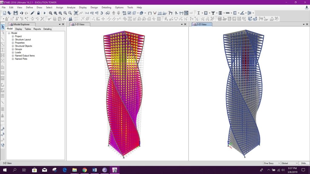
Courtesy: YouTube
- Step 5:
Evaluate and optimize the design. You can use different software tools to evaluate and optimize the design of the diagrid structure, such as Galapagos, Octopus, Optimo, etc. You can compare different design alternatives and find the optimal solution that minimizes the material consumption and maximizes the structural performance of the diagrid structure.
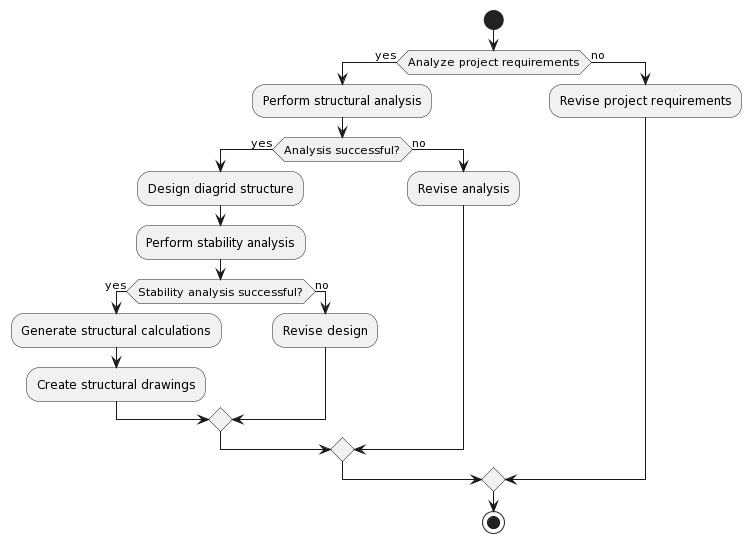
Flowchart of Structural Engineering Analysis and Design
The analysis and design process of dia grid structures typically follows a systematic flowchart. It starts with conceptualization and defining the design criteria, followed by parametric modeling and analysis. The structural analysis involves assessing the structural behavior, including stress distribution, deflections, and stability. Optimization techniques then used to refine the design, considering member sizes, connections, and material selection factors. The final step involves detailed design documentation and construction drawings.
A brief overview is given below:
Limitations of Diagrid Structures
-
The diagrid system has not yet been fully explored and requires skilled labor and expertise to install.
-
The diagrid system dominates the aesthetic appearance of the building, which may limit the design options and creativity.
-
The diagrid system may affect the floor-to-floor design as a single diagrid module spans over 2 to 6 floors.
-
The diagrid system may have high shear forces at the bolt connections of the nodes under lateral loads, which require careful design and detailing.
-
The diagrid system may have less redundancy than conventional systems, which means that a failure of a single member or node may have a significant impact on the overall stability and safety of the structure.
Conclusion
Diagrid structures represent a remarkable fusion of structural ingenuity and architectural aesthetics. Through parametric modeling, advanced analysis techniques, and innovative connection design, these structures offer unparalleled strength, efficiency, and visual appeal. As more sophisticated software tools and construction techniques continue to evolve, dia grid structures are poised to inspire awe and redefine the boundaries of structural engineering in the years to come.
References
- https://www.researchgate.net/publication/323573055_Biomimicry_as_an_Alternative_Approach_to_Sustainability
- https://aipublications.com/uploads/issue_files/1IJCMES-MAY20211-Parametric.pdf
- https://www.irjet.net/archives/V9/i3/IRJET-V9I3375.pdf
- https://www.jetir.org/papers/JETIR1904N18.pdf
- https://issuu.com/aipublications/docs/ijcmes-_1_may_-_june_2021
- https://creativecommons.org/licenses/by/4.0/
- https://drishti-svnit.github.io/CIVIL/documentation/Documentation%20Diagrid%20Structure-converted.pdf
- https://constructionor.com/diagrid-structural-system/
- https://link.springer.com/chapter/10.1007/978-3-030-55115-5_84